Tools/Beam Analysis/User guide

Arenith Beam Analysis

Model, solve and review a beam.

A concise guide to supports, loads, matrix-method analysis and result review. No installation or signup is required.

5 steps Length → Supports → Loads → Solve → Review Typical setup time: a few minutes

Before you start

Idealise the beam before entering data.

Decide the span, support conditions and applied actions first. The drawing updates as you enter the model, making misplaced supports and loads easier to spot.

Length and position
m
Point load
kN
Distributed load
kN/m
Moment
kNm
01

Define the model

Set the beam length and supports.

  1. Enter the total beam length in metres.
  2. Select a support type and enter its position measured from the left end.
  3. Use Add Support for additional supports.

Check: every support position must lie within the beam length. Confirm the drawing matches your intended structural idealisation.
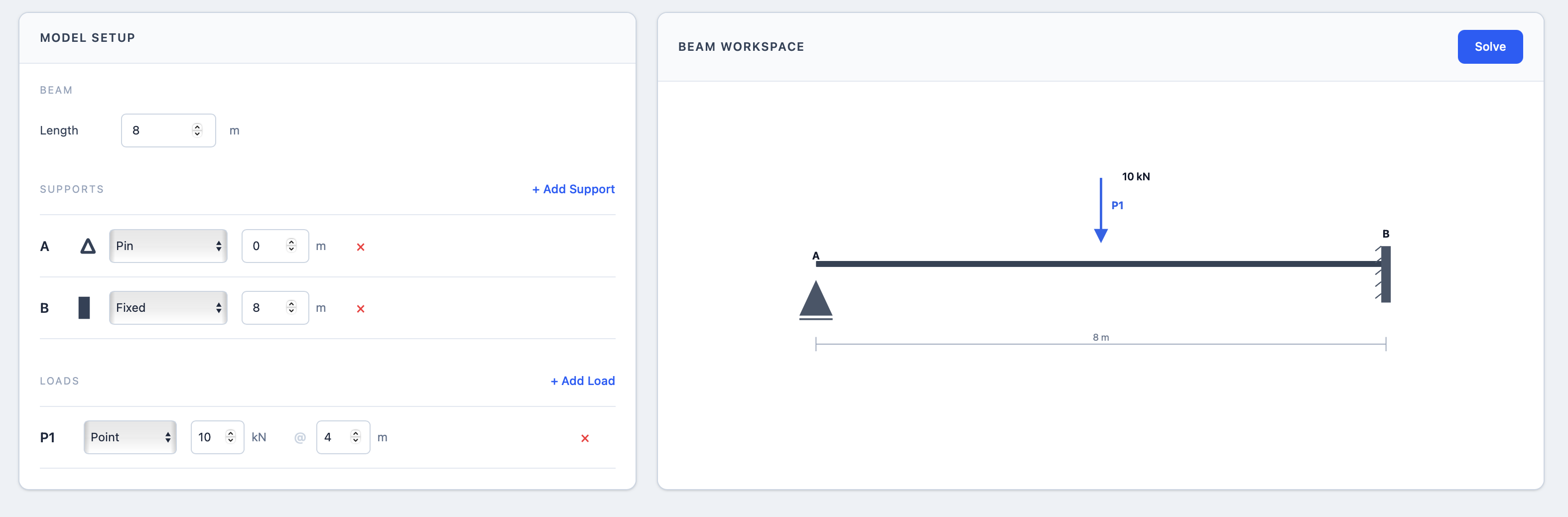
Arenith Beam Analysis workspace annotated to show beam length, supports, positions and the live model drawing 1 2 3 4
  1. 1Enter the total beam length.
  2. 2Choose each support type.
  3. 3Set its position from the left end.
  4. 4Confirm the drawing updates correctly.
02

Apply actions

Choose the load that represents your model.

Add another load when the beam has more than one applied action. Use the red remove control only for the row you want to delete.

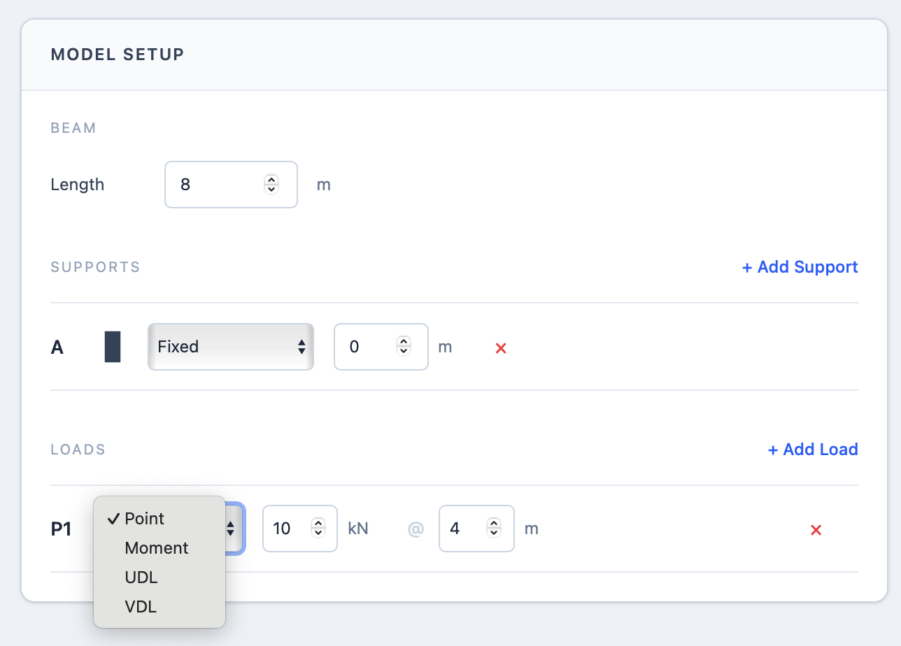
Load selector annotated to show the point load, moment, UDL and VDL choices1
  1. 1Open the selector and choose Point, Moment, UDL or VDL.

Choose a load type

Start by selecting the action that matches your idealised model.
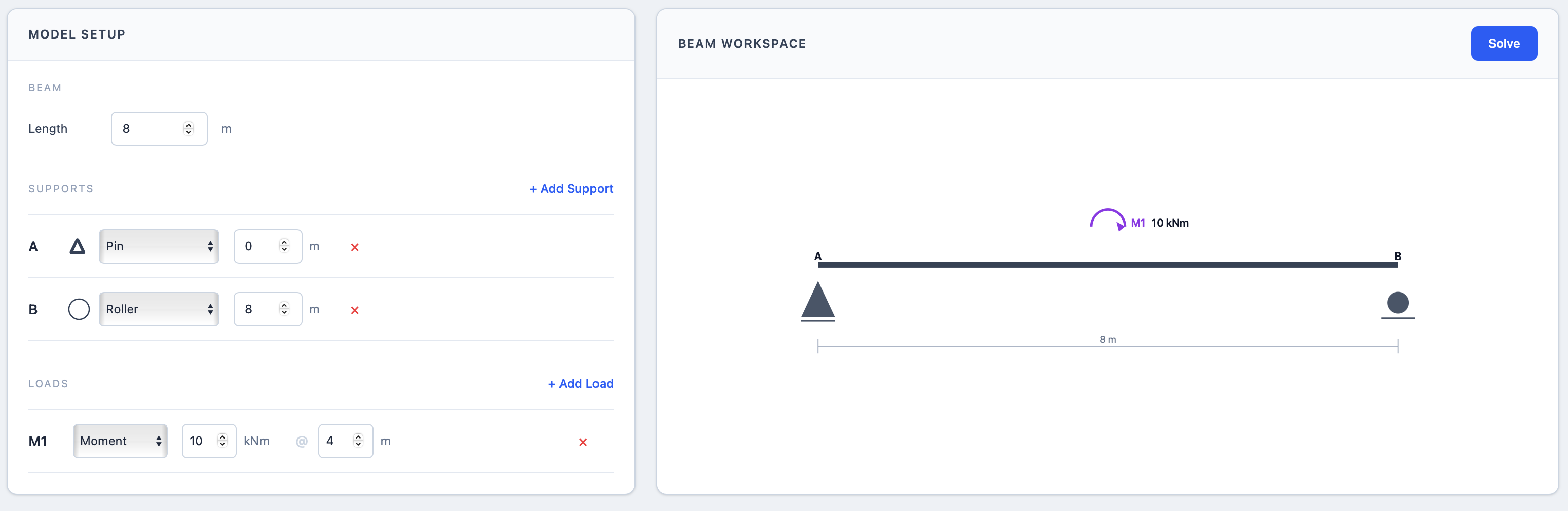
Moment load input and the resulting moment symbol annotated with numbered steps12
  1. 1Enter moment and position.
  2. 2Check its symbol and direction.

Moment

Magnitude is entered in kNm; position is measured in metres.
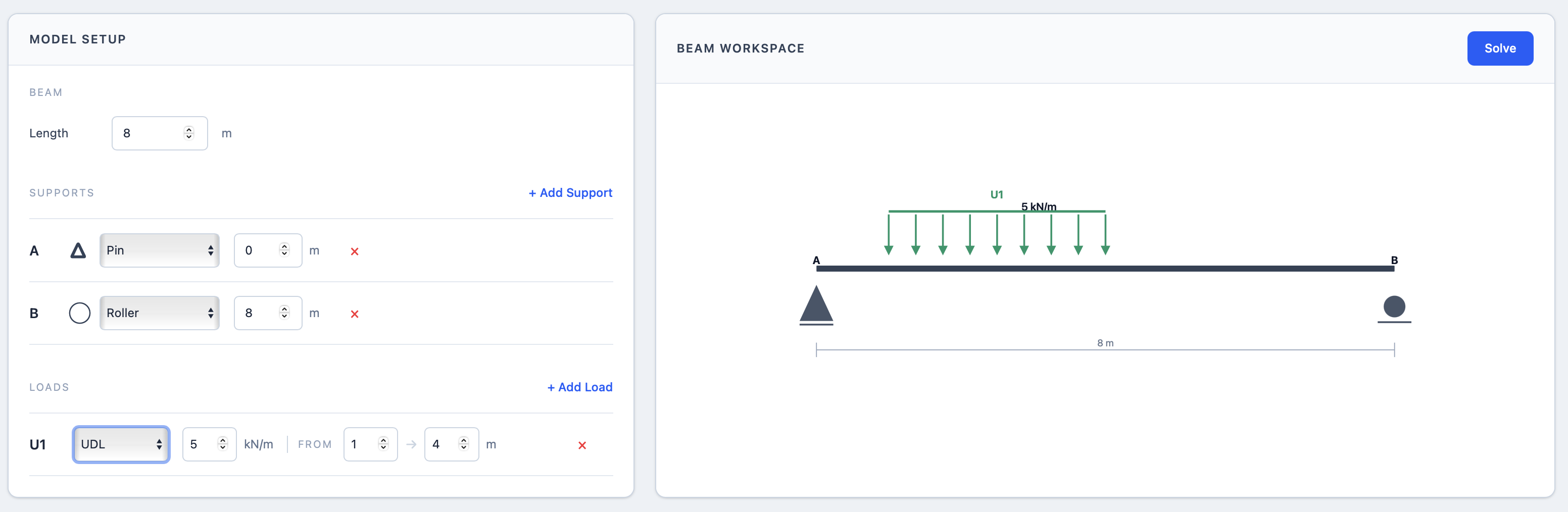
UDL inputs and constant distributed load drawing annotated with numbered steps12
  1. 1Enter intensity, start and end.
  2. 2Confirm the loaded range.

UDL

Use one constant intensity in kN/m across the defined range.
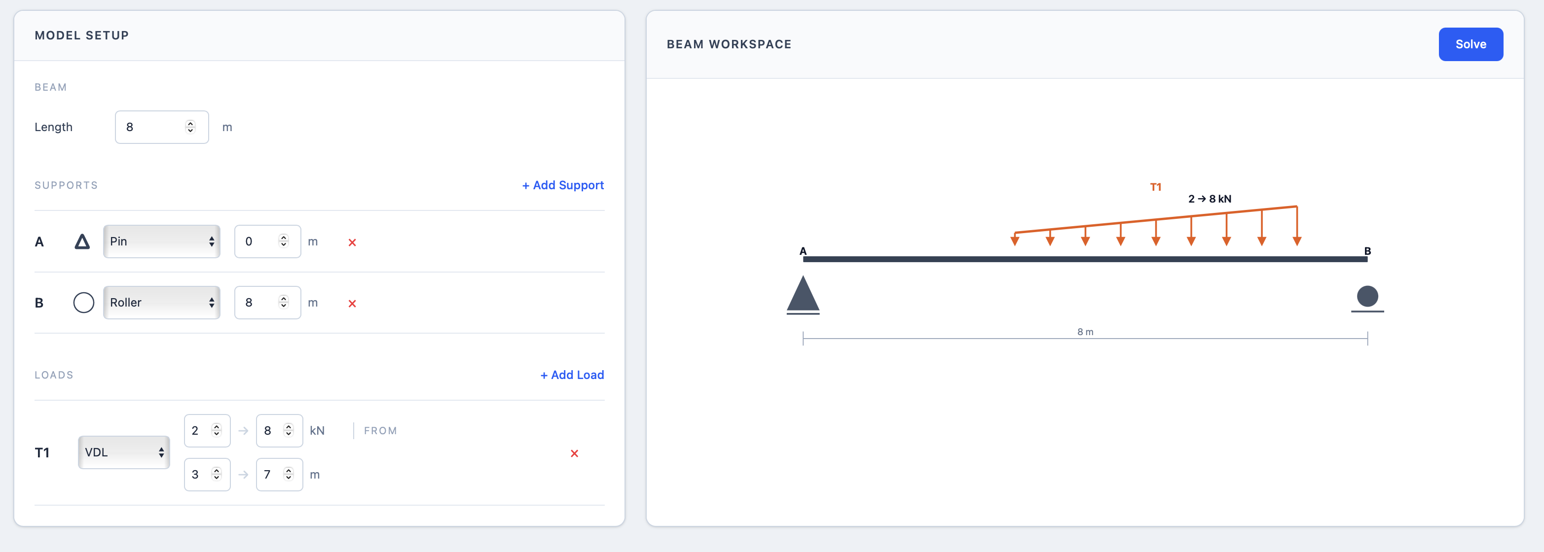
VDL inputs and varying distributed load drawing annotated with numbered steps12
  1. 1Enter both intensities and limits.
  2. 2Check the variation direction.

VDL

Define the start and end intensities in kN/m and their positions.

Position rule: load positions are measured from the left end. For distributed loads, the end position must be greater than the start position and both must remain within the beam.

03

Run the calculation

Inspect the model, then press Solve.

  1. Compare the drawn supports and loads with your intended model.
  2. Check all units, signs and positions.
  3. Press Solve.

If no results appear: check that the supports restrain the model and that every load and support position is valid.
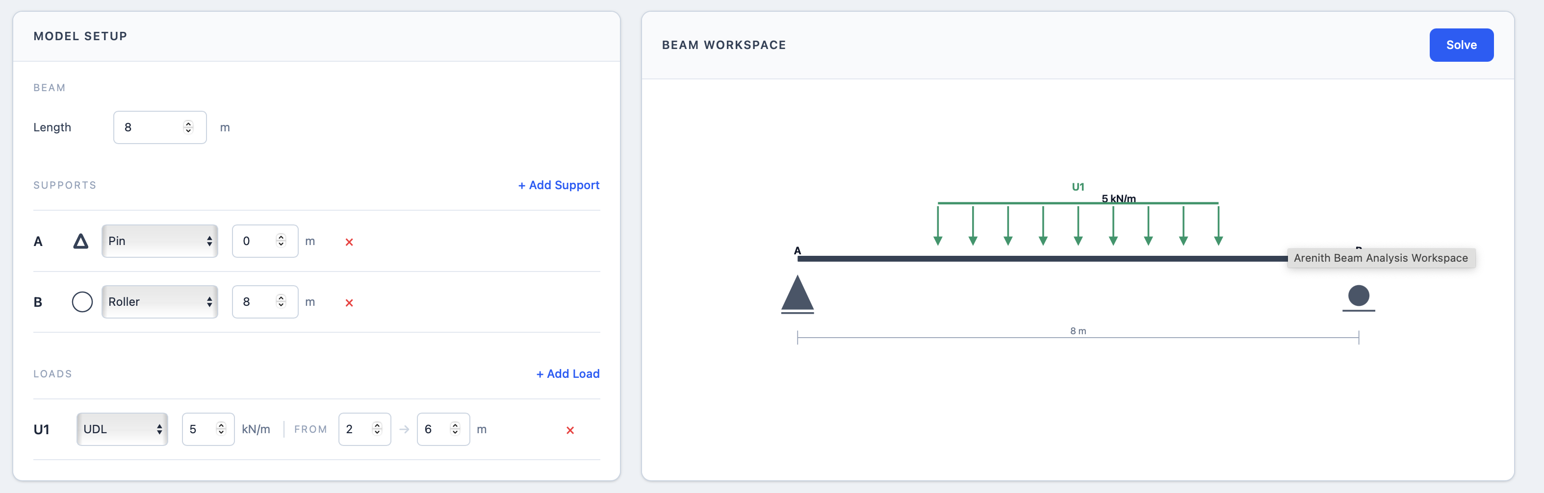
Completed beam model annotated to show the final model check and Solve button12
  1. 1Check supports, loading and dimensions.
  2. 2Press Solve only when the drawing is correct.
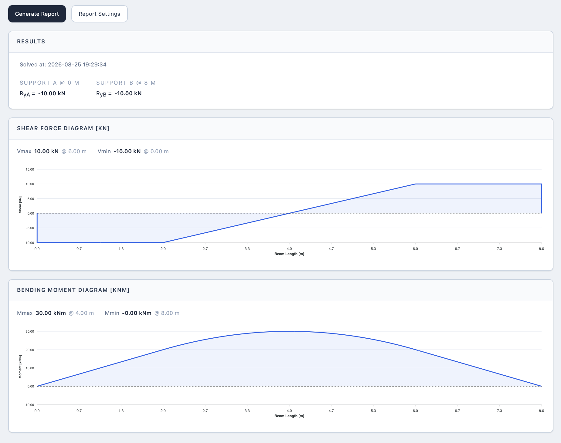
Beam analysis results annotated to show reactions, shear-force diagram and bending-moment diagram123
  1. 1Check support reactions and equilibrium.
  2. 2Review the shear-force diagram.
  3. 3Review the bending-moment diagram.
04

Interpret the results

Check equilibrium before using the diagrams.

  1. Review the support reactions and compare them with the applied loading.
  2. Inspect the shear-force diagram for expected changes at loads and supports.
  3. Inspect the bending-moment diagram and critical values.
  4. Use the report only after the model and results have been reviewed.

Engineering responsibility: the tool supports calculation work; it does not replace project-specific judgement, code checks or independent verification.

05

Quick troubleshooting

Most model errors come from three checks.

01

Stability

Supports must provide enough restraint for the model.

02

Position

Supports and loads must remain within the beam length.

03

Load range

A distributed load must end after it starts.

Need more than a preliminary model?

Use the tool freely. Bring Arenith the engineering problem.

Arenith provides structural design, finite-element analysis, independent technical checking and engineering automation for project-specific work.